In this post, we demonstrate a basic design process of Lateral Stanley Controller with time domain and frequency domain specifications.
Plant Model
The front axle based error state vehicle lateral dynamic model is used to run simulation and analyze tracking performance and robustness of stanley controller.
\[\begin{aligned} \underbrace{\begin{bmatrix} \dot{e}_1 \\\ddot{e}_1\\\dot{e}_2\\\ddot{e}_2\end{bmatrix}}_{\dot{x}_p} &= \underbrace{ \begin{bmatrix} 0 & 1 & 0 & 0 \\ 0 & -\frac{2C_{\alpha f} + 2C_{\alpha r}}{mV_x} & \frac{2C_{\alpha f} + 2C_{\alpha r}}{m}& \frac{2C_{\alpha r}(l_f + l_r)}{mV_x} \\ 0 & 0 & 0 & 1 \\ 0 & -\frac{2C_{\alpha f}l_f - 2C_{\alpha r} l_r}{I_zV_x}& \frac{2C_{\alpha f}l_f - 2C_{\alpha r}l_r}{I_z}& -\frac{2C_{\alpha r}l_r(l_f+l_r)}{I_zV_x}\end{bmatrix}}_{A_{p}} \underbrace{\begin{bmatrix} e_1\\\dot{e}_1\\e_2\\\dot{e}_2\end{bmatrix}}_{x_p}+ \underbrace{ \begin{bmatrix}0 & 0 \\ \frac{2C_{\alpha f}}{m} & \frac{2C_{\alpha r}(l_f+l_r)}{mV_x}-V_x\\ 0 & 0 \\ \frac{2C_{\alpha f} l_f}{I_z} & -\frac{2C_{\alpha r}l_r(l_f+l_r)}{I_zV_x}\end{bmatrix}}_{B_p} \underbrace{\begin{bmatrix} \delta \\ \dot{\psi_{des}}\end{bmatrix}}_{u}\\\\ \underbrace{\begin{bmatrix} e_1\\e_2\\\dot{e}_2\end{bmatrix}}_{y} &= \underbrace{ \begin{bmatrix}1&0&0&0\\0&0&1&0\\0&0&0&1\end{bmatrix}}_{C_p} \underbrace{\begin{bmatrix} e_1\\\dot{e}_1\\e_2\\\dot{e}_2\end{bmatrix}}_{x_p}+\underbrace{ \begin{bmatrix}0&0\\0&0\\0&0\end{bmatrix}}_{D_p} \underbrace{\begin{bmatrix} \delta \\ \dot{\psi_{des}}\end{bmatrix}}_{u} \end{aligned}\]
next, introduce a second-order actuator for the front wheel steering angle
\[\begin{aligned} \delta &= \frac {w^2_n}{s^2 + 2 \eta w_n + w^2_n } \delta_c \\ \ddot{\delta} &= -2\eta w_n\dot{\delta} + w^2_n(\delta_c - \delta) \end{aligned}\]
The plant model with actuator dynamics could be express as follow
\[\begin{aligned} \underbrace{\begin{bmatrix} \dot{e}_1\\\ddot{e}_1\\\dot{e}_2\\\ddot{e}_2\\ \dot{\delta} \\ \ddot{\delta}\end{bmatrix}}_{\dot{x}_p} &= \underbrace{ \begin{bmatrix} 0 & 1 & 0 & 0 & 0 & 0 \\ 0 & -\frac{2C_{\alpha f} + 2C_{\alpha r}}{mV_x} & \frac{2C_{\alpha f} + 2C_{\alpha r}}{m}& \frac{2C_{\alpha r}(l_f + l_r)}{mV_x} & \frac{2C_{\alpha f}}{m} & 0\\ 0 & 0 & 0 & 1 & 0 & 0\\ 0 & -\frac{2C_{\alpha f}l_f - 2C_{\alpha r} l_r}{I_zV_x}& \frac{2C_{\alpha f}l_f - 2C_{\alpha r}l_r}{I_z}& -\frac{2C_{\alpha r}l_r(l_f+l_r)}{I_zV_x} & \frac{2C_{\alpha f} l_f}{I_z} &0\\ 0&0&0&0&0&1\\ 0&0&0&0&-w^2_n&-2\eta w_n\end{bmatrix}}_{A_{p}} \underbrace{\begin{bmatrix} e_1\\\dot{e}_1\\e_2\\\dot{e}_2\\\delta\\\dot{\delta}\end{bmatrix}}_{x_p} + \underbrace{ \begin{bmatrix}0 & 0 \\ 0 & \frac{2C_{\alpha r}(l_f+l_r)}{mV_x}-V_x\\ 0 & 0 \\ 0 & -\frac{2C_{\alpha r}l_r(l_f+l_r)}{I_zV_x} \\ 0 & 0 \\ w^2_n & 0\end{bmatrix}}_{B_p} \underbrace{\begin{bmatrix} \delta_c\\ \dot{\psi_{des}}\end{bmatrix}}_{u} \\\\ \underbrace{\begin{bmatrix} e_1\\e_2\\\dot{e}_2\end{bmatrix}}_{y} &= \underbrace{ \begin{bmatrix}1&0&0&0&0&0\\0&0&1&0&0&0\\0&0&0&1&0&0\end{bmatrix}}_{C_p} \underbrace{\begin{bmatrix} e_1\\\dot{e}_1\\e_2\\\dot{e}_2\\\delta\\\dot{\delta}\end{bmatrix}}_{x_p}+\underbrace{ \begin{bmatrix}0&0\\0&0\\0&0\end{bmatrix}}_{D_p} \underbrace{\begin{bmatrix} \delta_c \\ \dot{\psi_{des}}\end{bmatrix}}_{u} \end{aligned}\]
Stanley Controller Model
The control law of stanley controller is:
\[\begin{aligned}\delta &= k_{openloop} \cdot arctan( \kappa L) - arctan(k_{e_1}\cdot \frac{e_1}{V_x}) - k_{e_2}\cdot e_2-k_{\dot{e}_2}\cdot \dot{e}_2\\ & \approx k_{openloop} \cdot \kappa L - \frac{k_{e_1}}{V_x}\cdot e_1 - k_{e_2}\cdot e_2-k_{\dot{e}_2}\cdot \dot{e}_2\end{aligned}\]
The common state space representation of stanley controller could be expressed as
\[\begin{aligned} \underbrace{\begin{bmatrix} \dot x_{c_1} \\ \dot x_{c_2} \end{bmatrix}}_{\dot x_c} &= \underbrace{\begin{bmatrix} 0 & 0 \\ 0 & 0\end{bmatrix}}_{A_c} \underbrace{\begin{bmatrix} x_{c_1} \\ x_{c_2}\end{bmatrix}}_{x_c} + \underbrace{\begin{bmatrix} 0 & 0 & 0 \\ 0 & 0 & 0\end{bmatrix}}_{B_{c_1}} \underbrace{\begin{bmatrix} e_1\\e_2\\\dot{e}_2\end{bmatrix}}_{y} + \underbrace{\begin{bmatrix} 0 & 0 \\ 0 & 0 \end{bmatrix}}_{B_{c_2}} \underbrace{\begin{bmatrix} \kappa \\ \dot{\psi}_{des} \end{bmatrix}}_{r} \\\\ \underbrace{\begin{bmatrix} \delta \\ \dot{\psi_{des}}\end{bmatrix}}_{u} &= \underbrace{\begin{bmatrix} 0 & 0 \\ 0 & 0\end{bmatrix}}_{C_c} \underbrace{\begin{bmatrix} x_{c_1} \\ x_{c_2}\end{bmatrix}}_{x_c} + \underbrace{\begin{bmatrix} -\frac{k_{e_1}}{V_x} & -k_{e_2} & -k_{\dot{e}_2} \\ 0 & 0 & 0 \end{bmatrix}}_{D_{c_1}} \underbrace{\begin{bmatrix} e_1\\e_2\\\dot{e}_2\end{bmatrix}}_{y} + \underbrace{\begin{bmatrix} k_{ol}L & 0 \\ 0 & 1 \end{bmatrix}}_{D_{c_2}} \underbrace{\begin{bmatrix} \kappa \\ \dot{\psi}_{des} \end{bmatrix}}_{r} \end{aligned}\]
Stanley Controller Design Chart
Stability and Performance Specifications
| Frequency Domain Specification |
|---|
| Small error at low frequency for command tracking and disturbance rejection |
| Robust to noise, high frequency un-modeled dynamics |
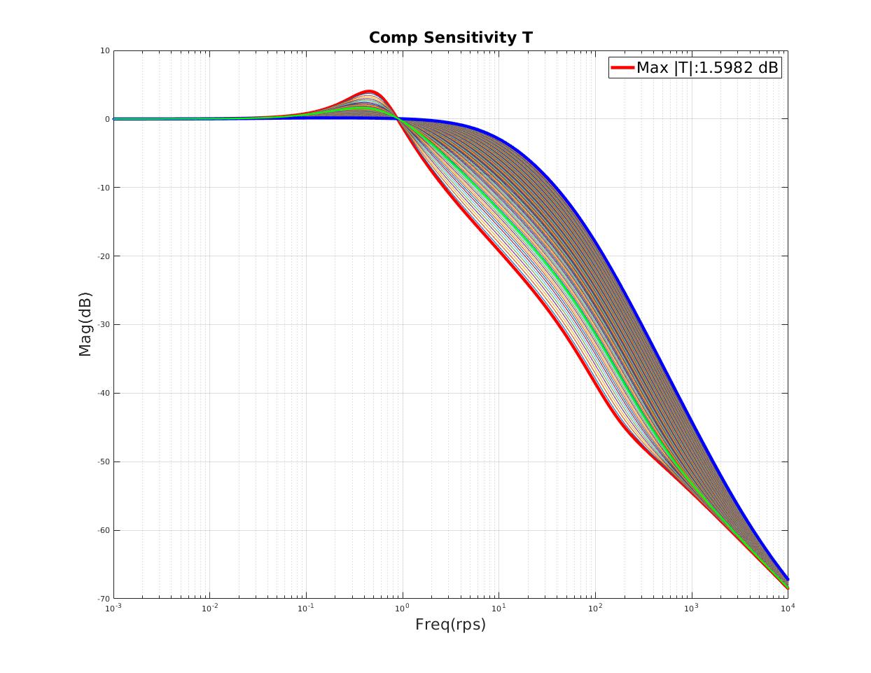
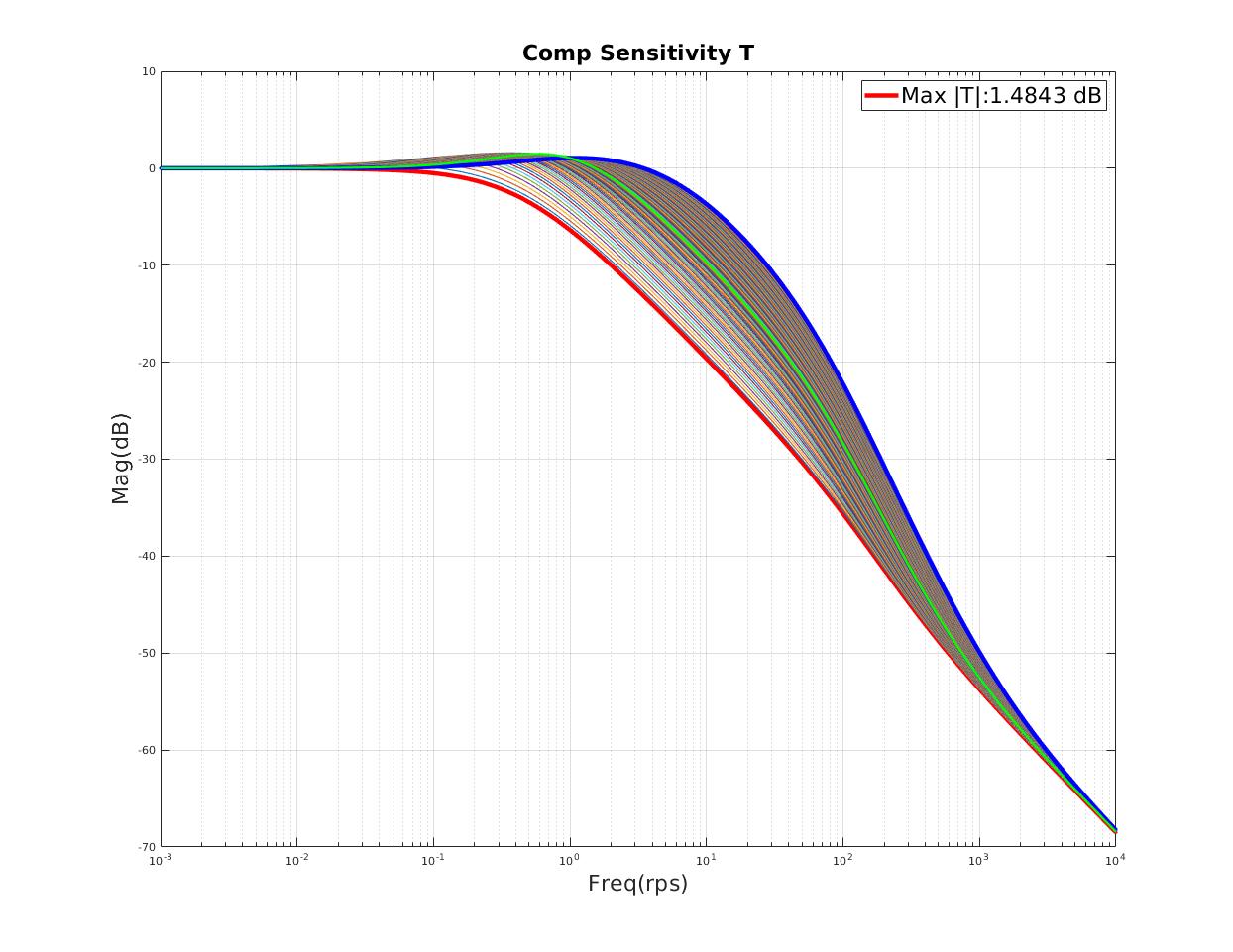
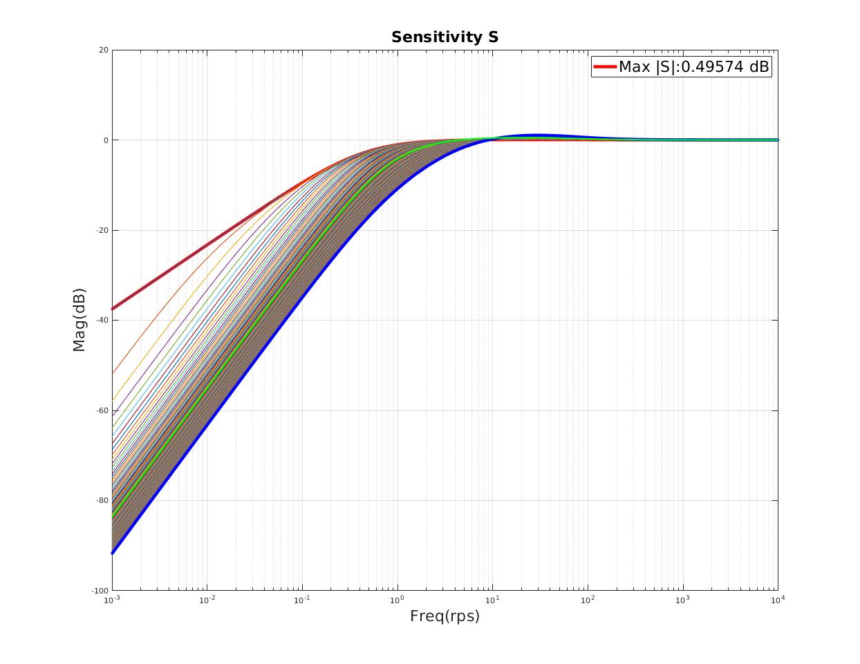
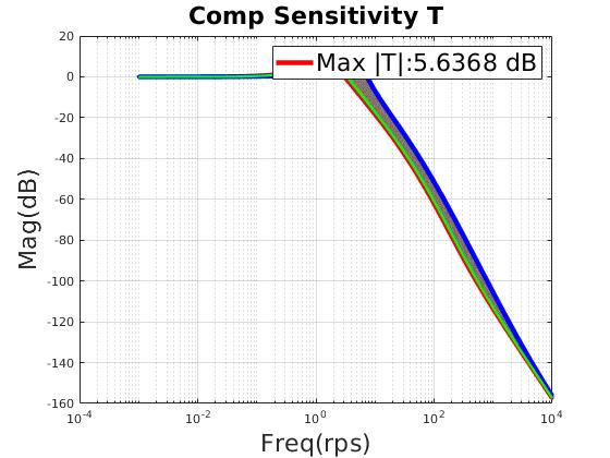
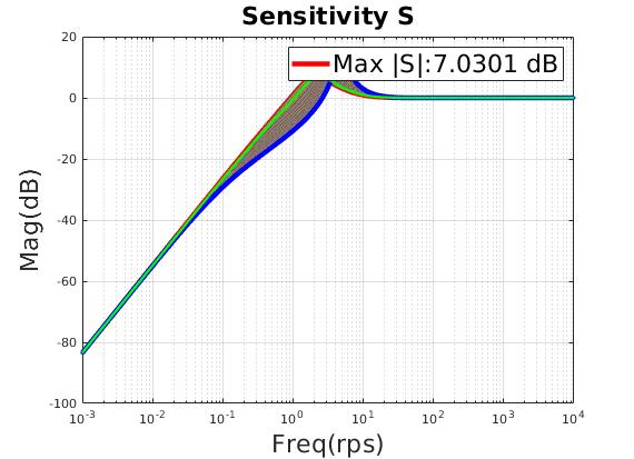
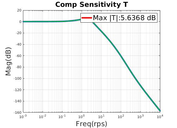
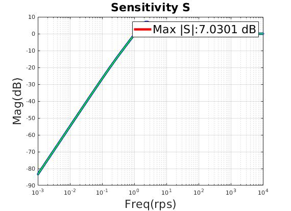
| Small resonant peak on Sensitivity and Complementary Sensitivity |
| Reasonable bandwidth of closed-loop system |
| Frequency Domain Specification | |
|---|
| Robust to actuator dynamics | \(e^{-t_d s}\frac{w^2_n}{s^2 + 2 \eta w_n s + w^2_n} \text{ ,where } t_d = 0.1 ,\eta = 1.0, w_n = 6.0\) |
| Robust to extra time delays | \(t_{\text{extra delay}} = 0.1s\) |
| Time Domain Specification | |
|---|
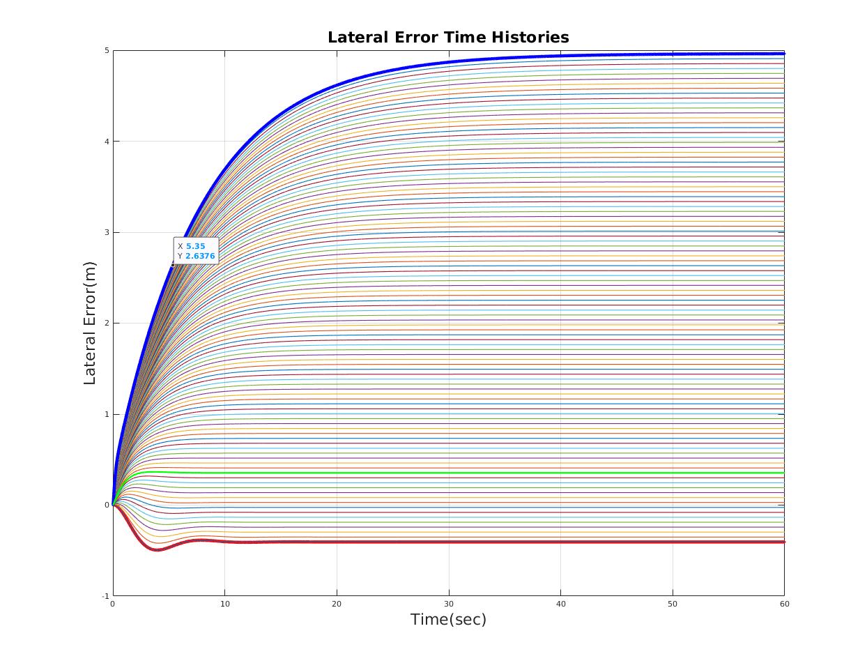
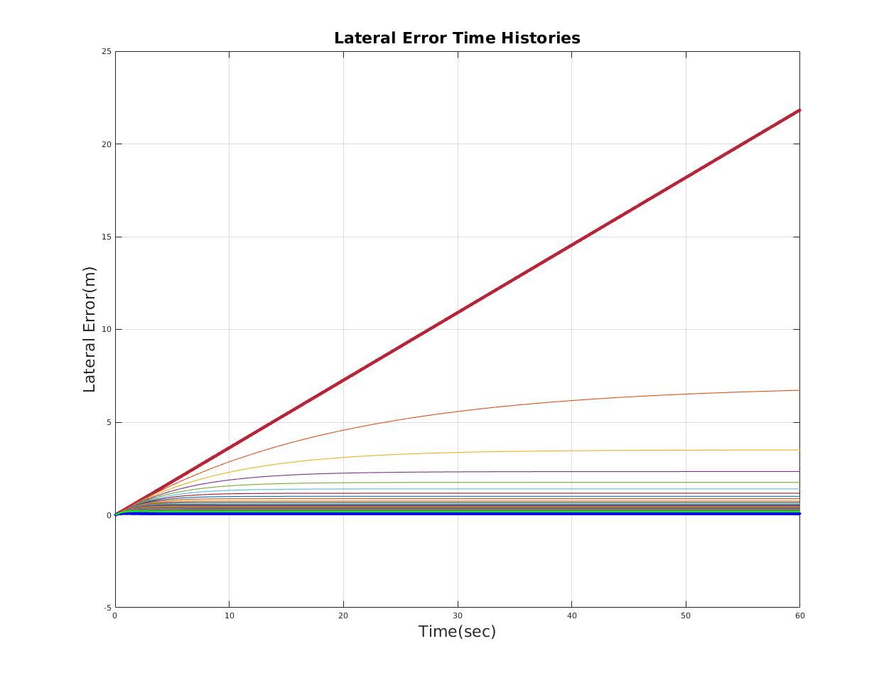
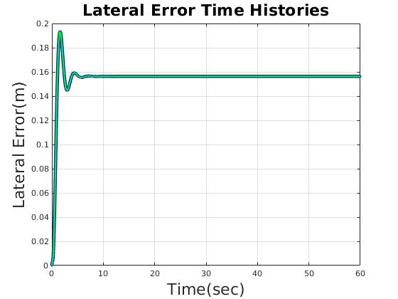
| Lateral Error(m) | less than 0.2m |
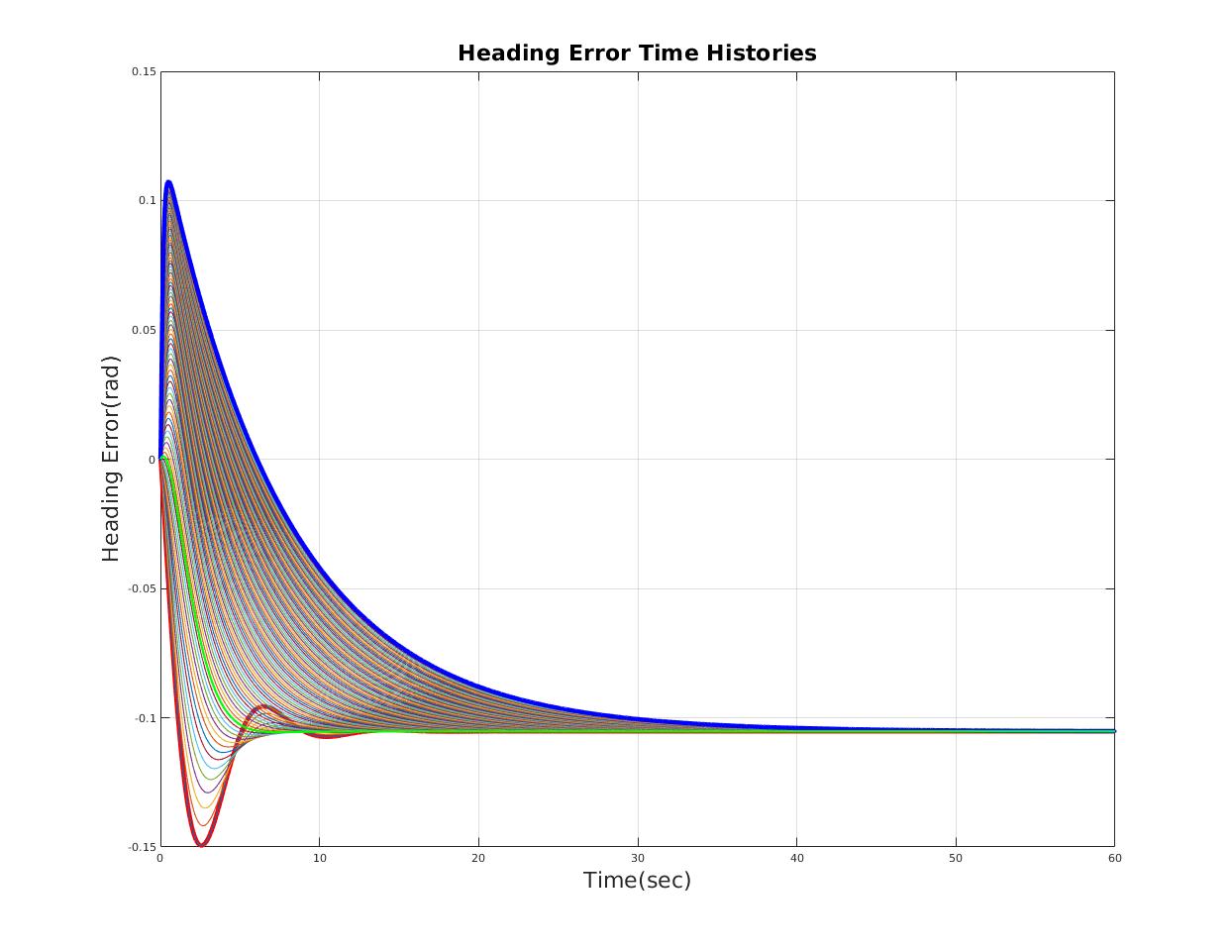
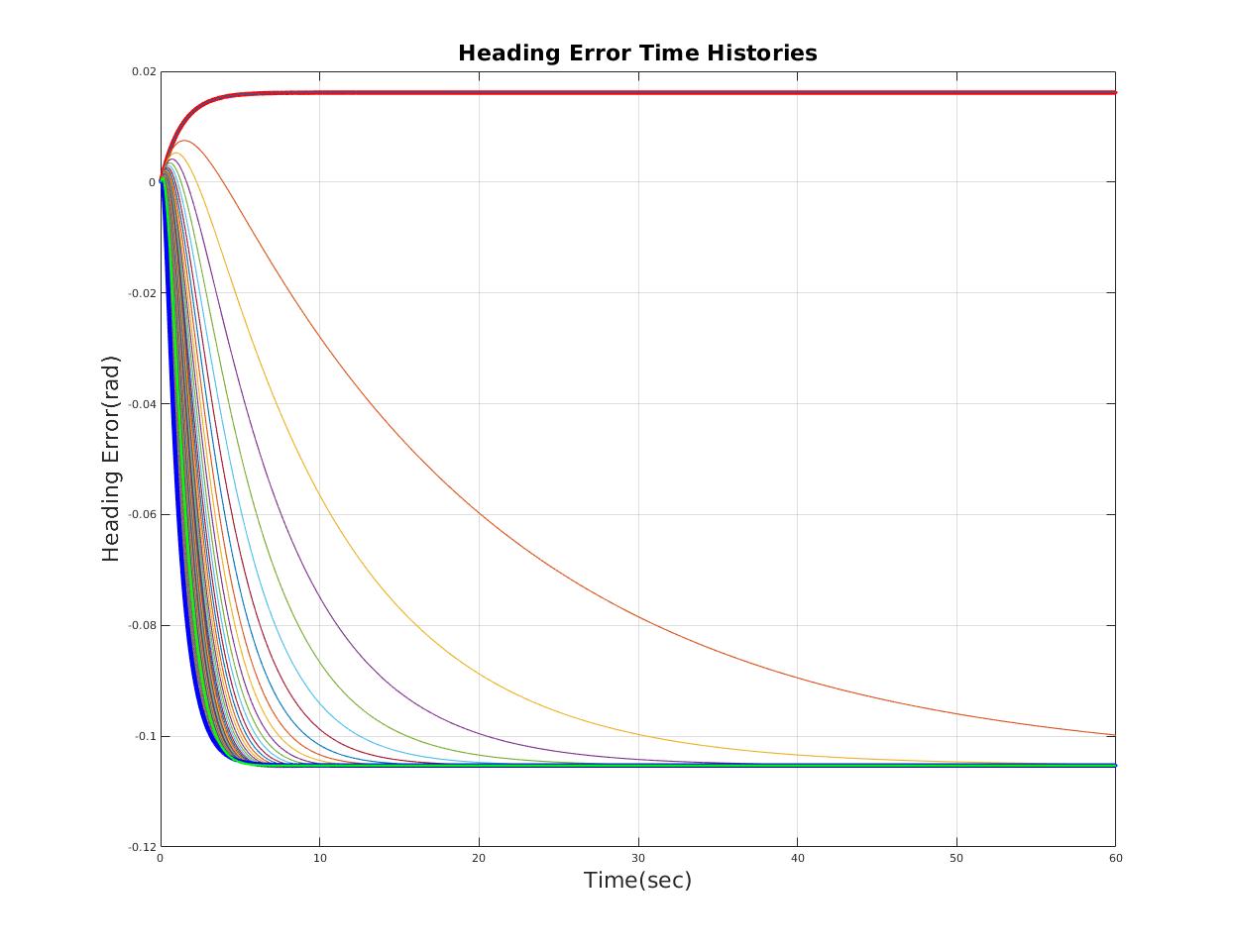
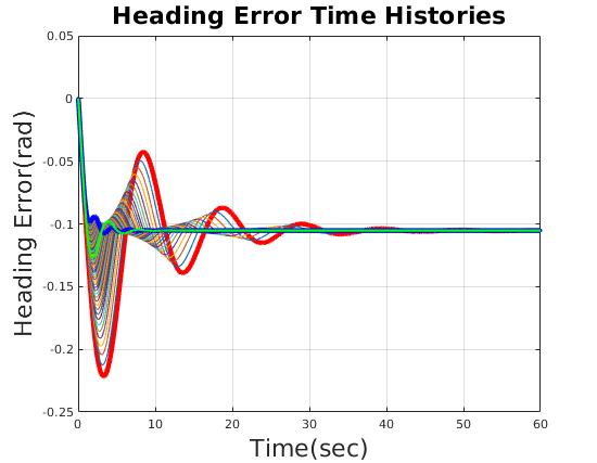
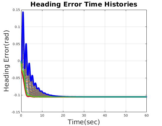
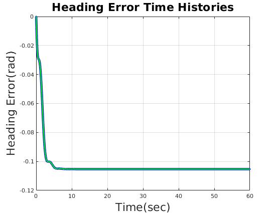
| Heading Error(rad) | less than 0.17 rad (10 deg) |
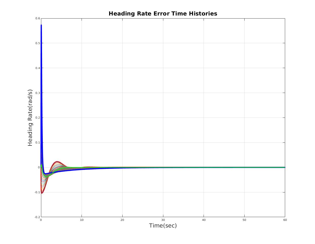
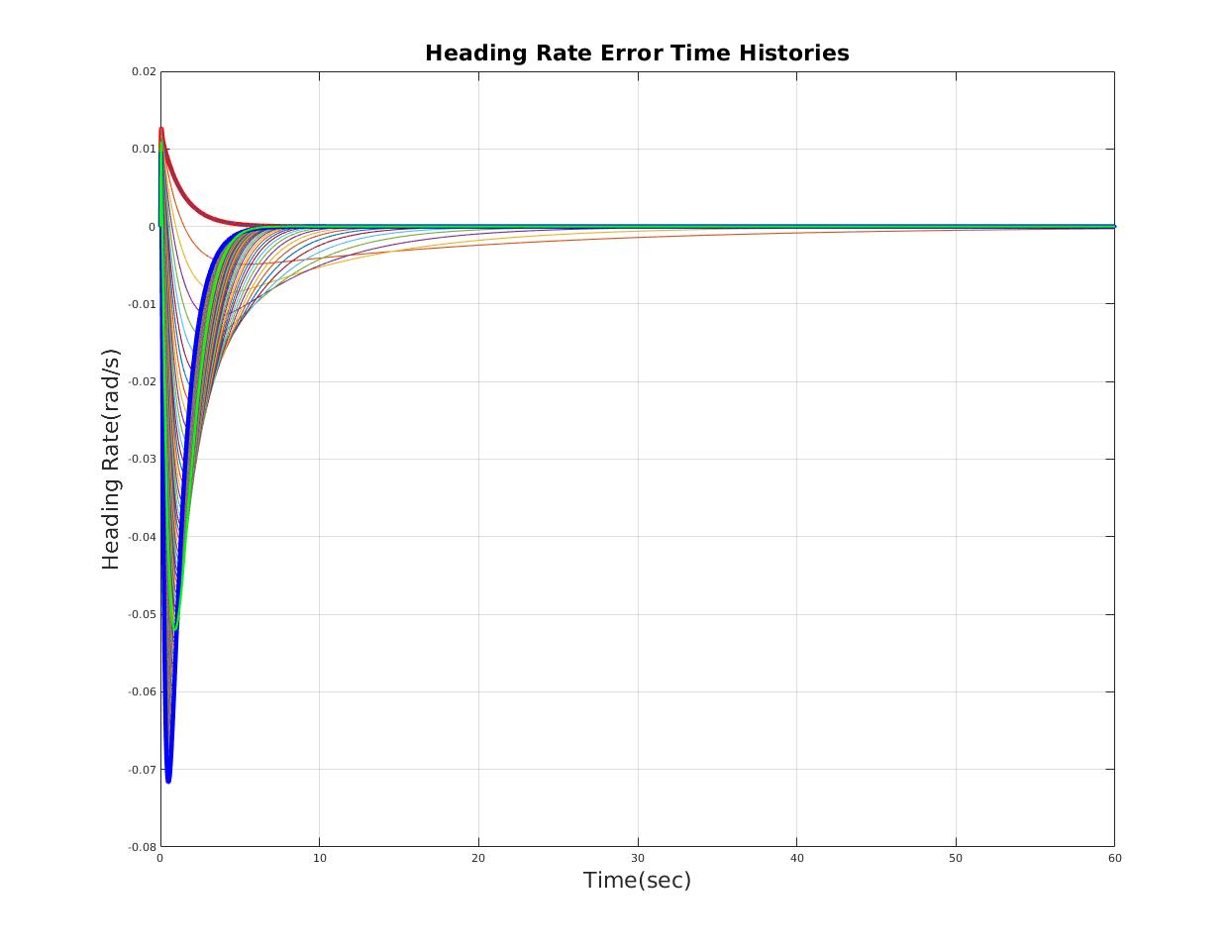
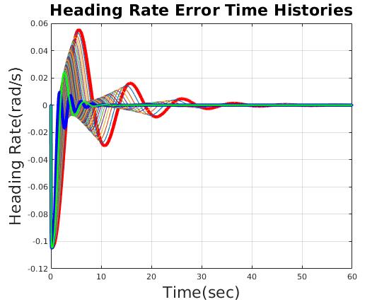
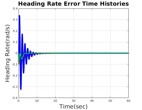
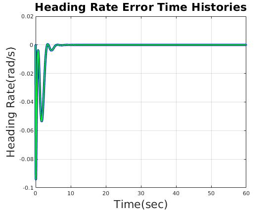
| Heading Rate Error (rad/s) | less than 0.1 rad/s |
Design Without Actuator Dynamics(Actuator Dynamics as Equivalent Uncertainty)
| Design Heading Gain (with a fix lateral gain) |
|---|
|
|
|
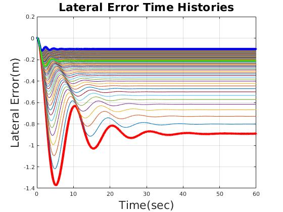
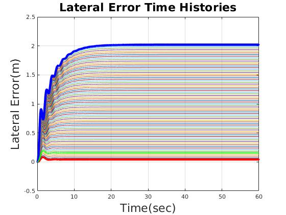
| Time domain performance varies with scale factor of heading gain |
|
|
|
|
|
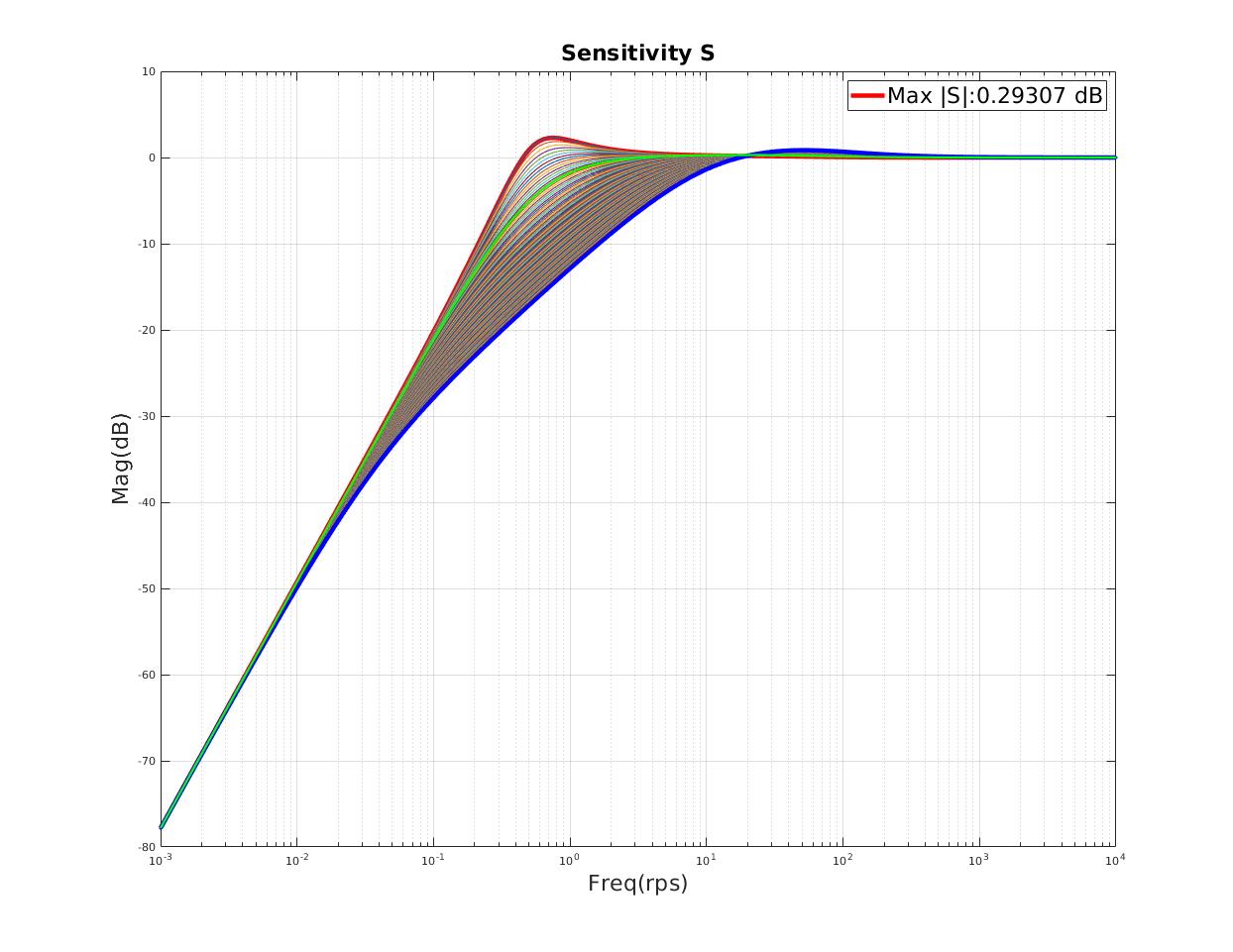
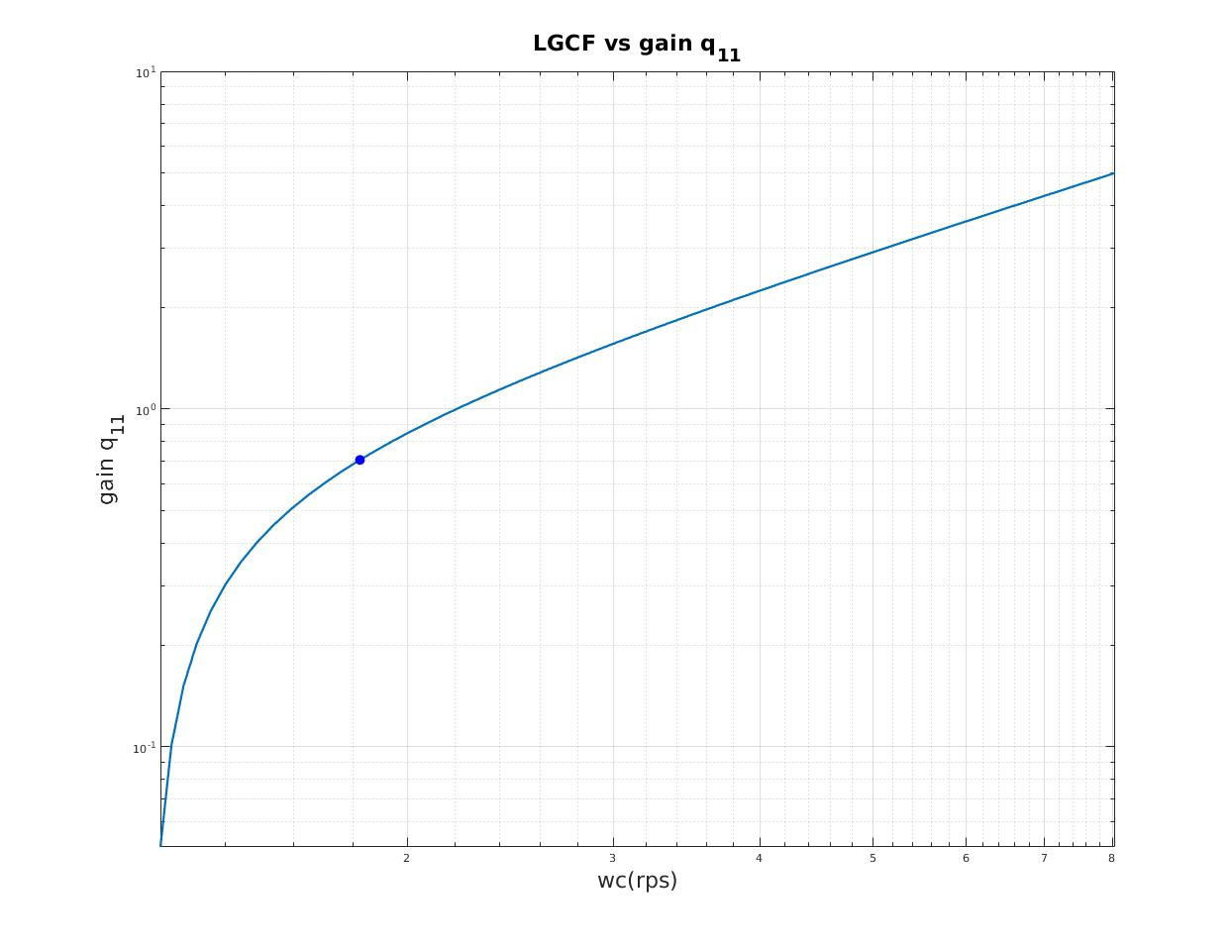
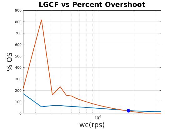
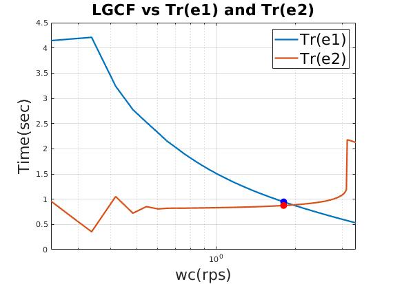
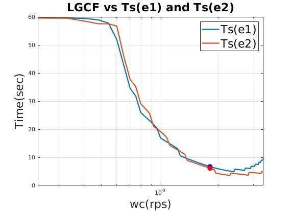
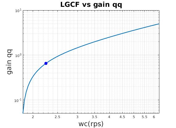
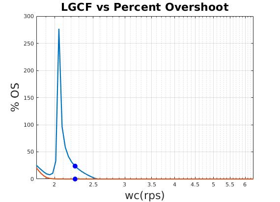
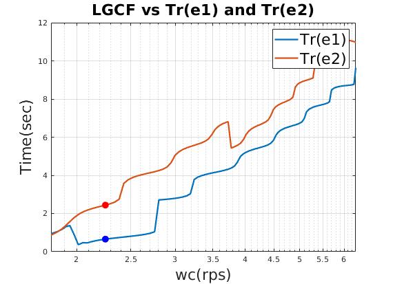
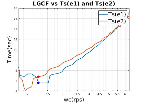
| Loop gain crossover frequency (LGCF) is a important design index in frequency domain analysis |
|
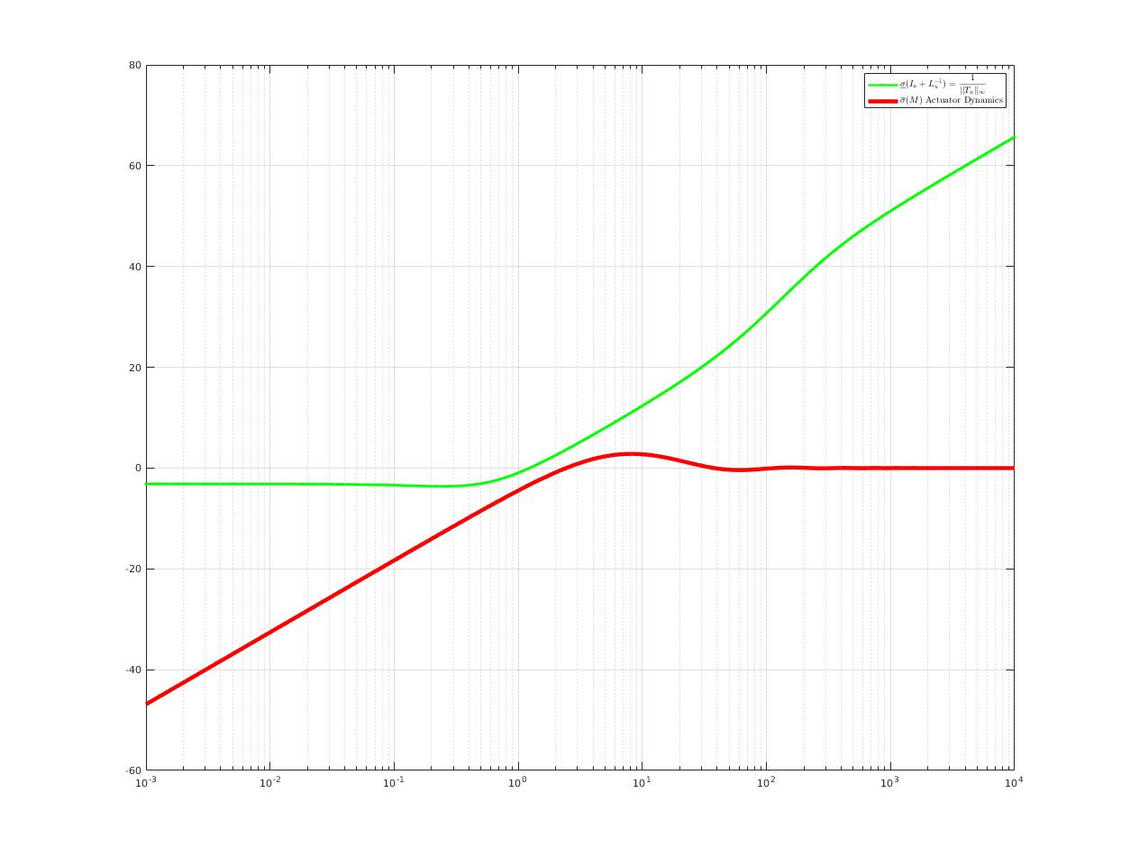
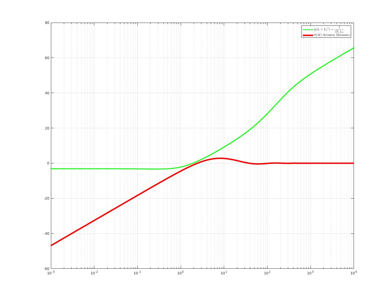
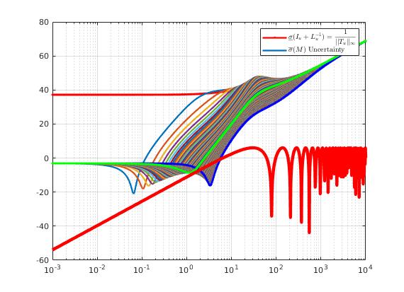
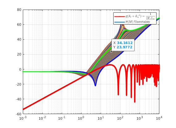
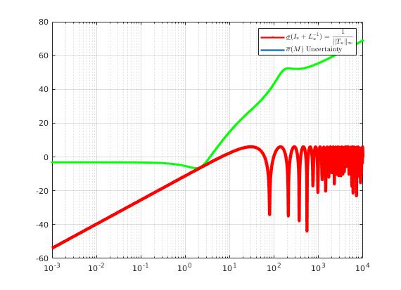
| Stability Test: Since no overlap, according to Small Gain Theorem, closed-loop system with actuator is guaranteed to be stable. |
| Design Lateral Gain (with a fix heading gain) |
|
|
|
| Time domain performance varies with scale factor of heading gain |
|
|
|
|
|
|
| Final Design |
|
|
|
|
|
|
Design With Actuator Dynamics (Model Pure Delay as Equivalent Uncertainty)
| Design Lateral Gain (with zero heading gain) |
|---|
|
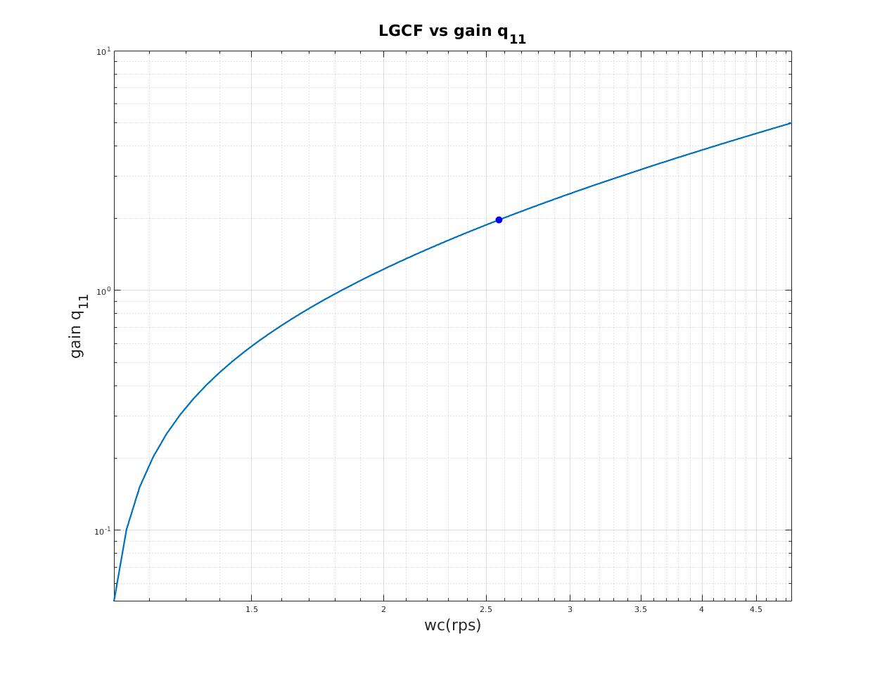
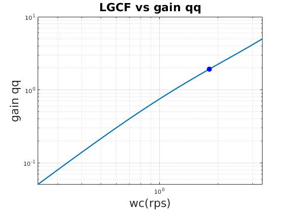
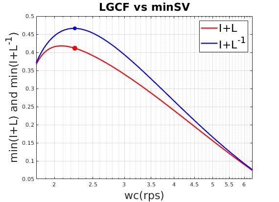
| Relation between loop gain crossover frequency (LGCF) and scale factor of lateral gain (qq) |
|
|
|
|
|
|
| Reasonable time domain performance |
|
|
|
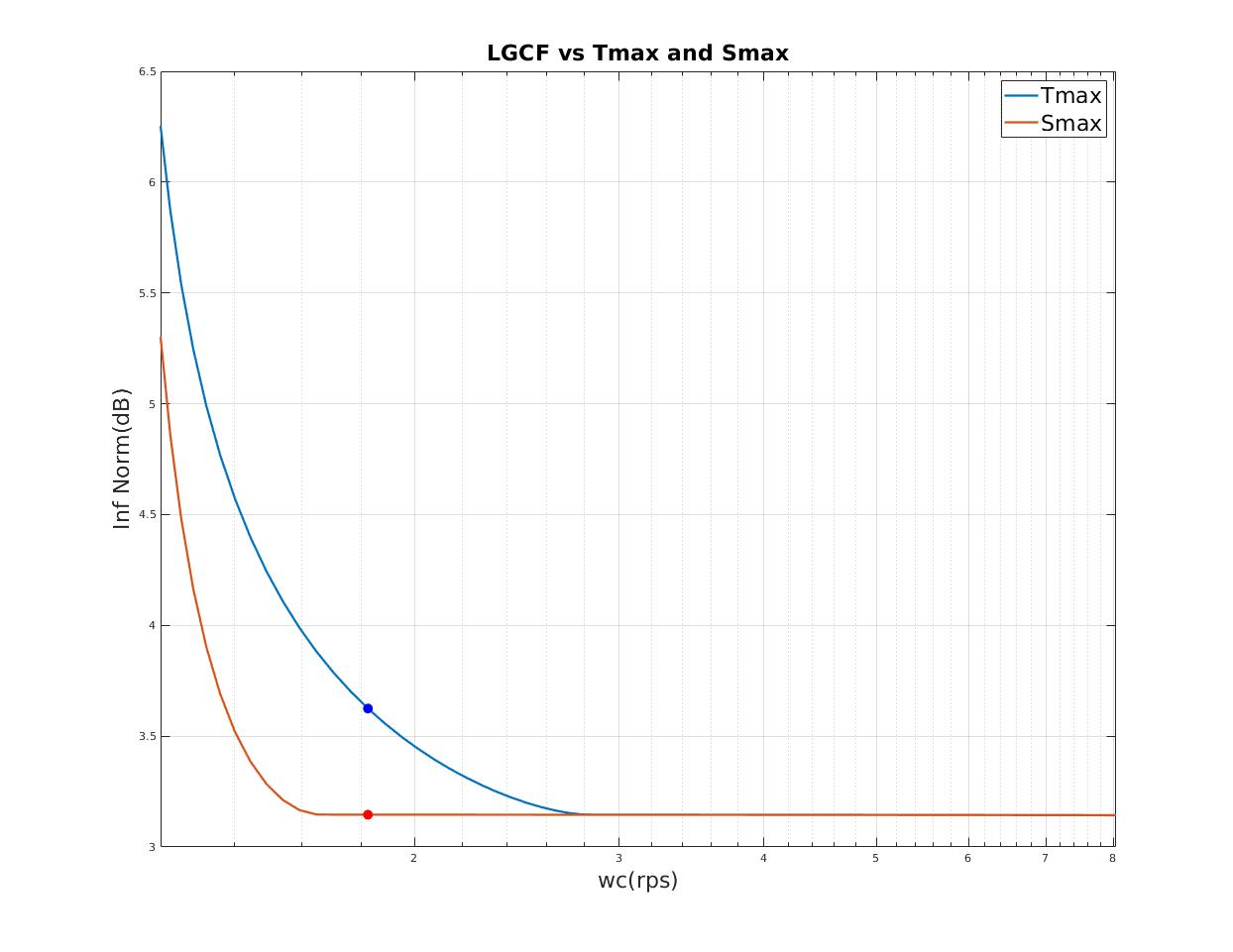
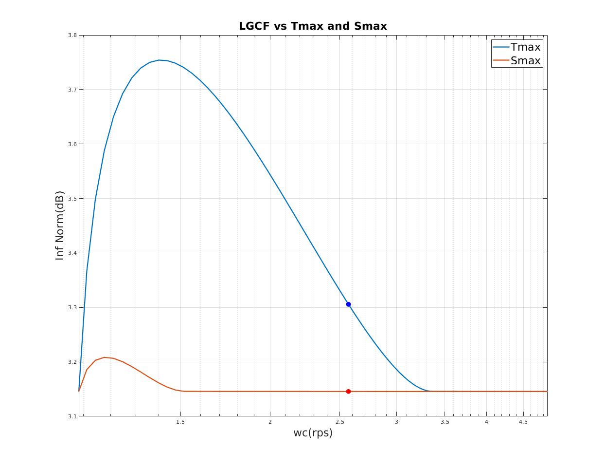
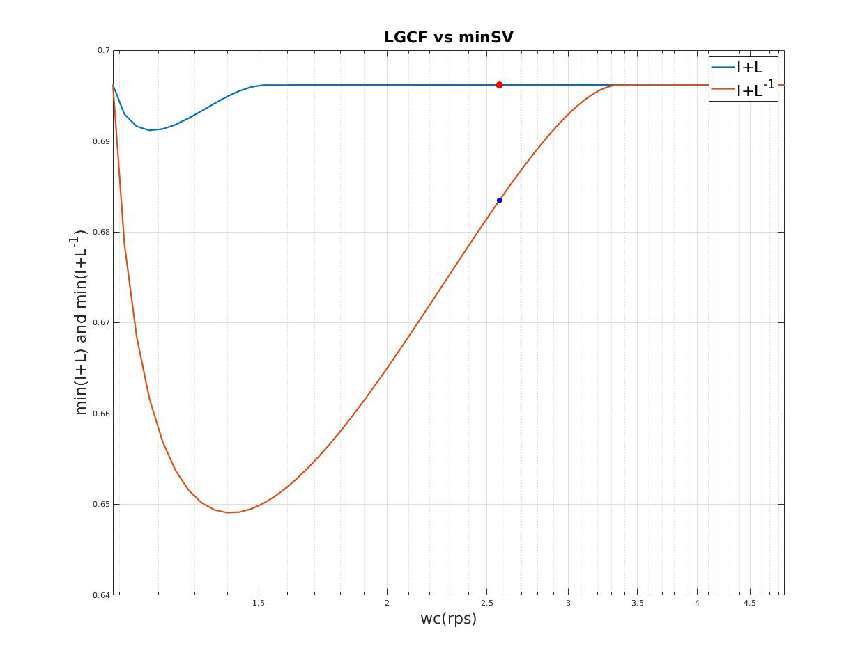
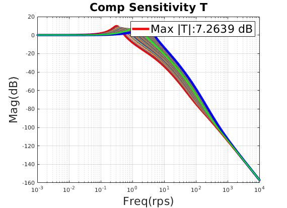
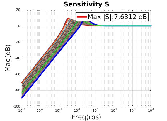
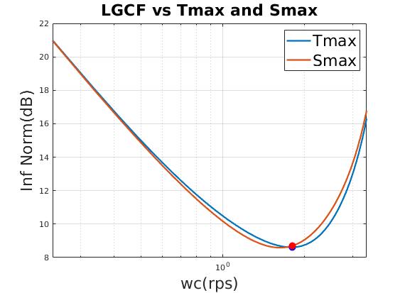
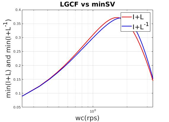
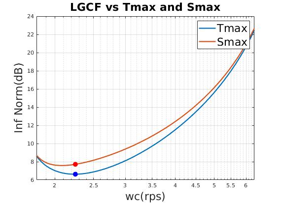
| Minimum $T_{max},S_{max}$ indicates minimum peak resonant |
|
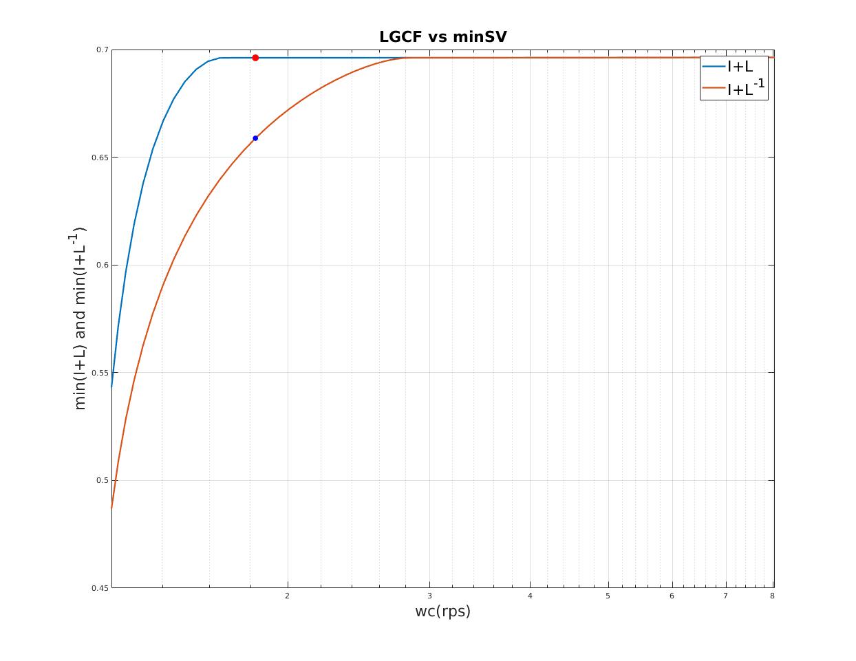
| Maximum $I+L ,I+L^{-1}$ indicates maximum singular value stability margin |
|
| Design Heading Gain (with a fixed lateral gain designed above) |
|
| Relation between loop gain crossover frequency (LGCF) and scale factor of heading gain (qq) |
|
|
|
|
|
|
| Reasonable time domain performance |
|
|
|
| Select minimum $T_{max}$ as final design point |
|
| Select maximum $I+L^{-1}$ as final design point |
|
| current configuration is robust to actuator dynamics and extra delay |
| Final Design |
|
|
|
|
|
|
| Design Specifications | | |
|---|
| Lateral Gain $k_{e_1}$ | Heading Gain $k_{e_2}$ | Open-loop Gain (a copy of heading gain) $k_{ol}$ |
| 1.5354 | 0.722 | 0.722 |
| Time Domain Performance | | |
|---|
| | Max Abs | Steady-state |
| lateral error (m) | 0.193 | 0.156 |
| heading error (rad) | 0.105 | 0.105 |
| heading rate error (rad/s) | 0.094 | 0.0 |
| | lateral | heading |
| Rise Time (s)<10 - 90%> | 0.65 | 2.44 |
| Settle Time(s)<2%> | 3.63 | 4.79 |
| Percent Overshoot (%) | 23.7 | 0.0 |
| Frequency Domain Performance | |
|---|
| Max $\lVert T \rVert $ (dB) | 5.63 |
| Max $\lVert S \rVert $ (dB) | 7.03 |
| $\underline {\sigma} (I + L)$ | 0.41145 |
| $\underline {\sigma} (I + L^{-1})$ | 0.46631 |
| | Gain Margin (dB), Phase Margin (deg) |
|---|
| Singular Value Stability Margin | [-5.4542 4.6043], 26.9656 |
| Robust to Actuator | $e^{-t_d s}\frac{w^2_n}{s^2 + 2 \eta w_n s + w^2_n} \text{ ,where } t_d = 0.1 ,\eta = 1.0, w_n = 6.0$ |
| Robust to Extra Delay (s) | $t_{\text{extra delay}} = 0.1s$ |
Simulation Results
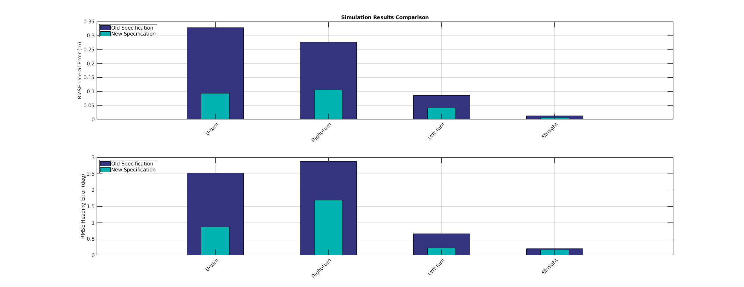
| Scenario | U-turn | U-turn | Right-turn | Right-turn | Left-turn | Left-turn | Straight | Straight |
|---|
| Specification | Old | New | Old | New | Old | New | Old | New |
| RMSE lateral error (m) | 0.3283 | 0.0931 | 0.2763 | 0.105 | 0.0859 | 0.0413 | 0.0133 | 0.0057 |
| 99 Percentile Max absolute lateral error (m) | 0.5119 | 0.1479 | 0.4938 | 0.2828 | 0.1673 | 0.0755 | 0.0464 | 0.0081 |
| RMSE heading error (rad) | 0.044 | 0.0151 | 0.0502 | 0.0294 | 0.0115 | 0.0039 | 0.0036 | 0.0028 |
| 99 Percentile Max absolute heading error(rad) | 0.0789 | 0.0558 | 0.0941 | 0.0715 | 0.0206 | 0.008 | 0.0126 | 0.0068 |
| Simulation Results Comparison |
|---|
|
Road Test Results
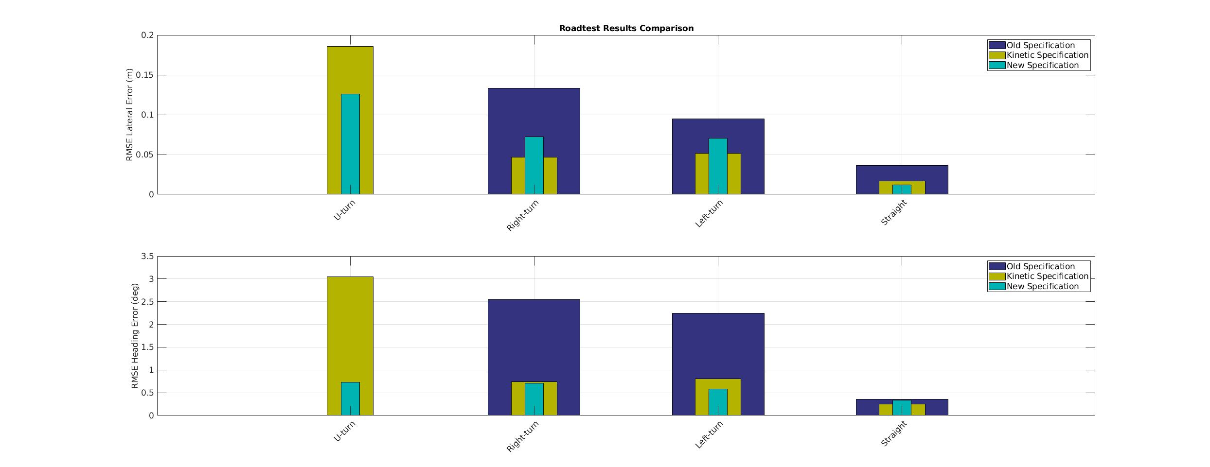
| Scenario | U-turn | U-turn | U-turn | Right-turn | Right-turn | Right-turn | Left-turn | Left-turn | Left-turn | Straight | Straight | Straight |
|---|
| Specification | Old | Kinetic | New | Old | Kinetic | New | Old | Kinetic | New | Old | Kinetic | New |
| RMSE lateral error (m) | NO_DATA | 0.1855 | 0.1258 | 0.1332 | 0.0465 | 0.0722 | 0.0949 | 0.0515 | 0.0703 | 0.0363 | 0.017 | 0.0118 |
| 99 PercentileMax lateral error (m) | NO_DATA | 0.297 | 0.0704 | 0.0518 | 0.0166 | 0.1306 | 0.1564 | 0.083 | 0.0111 | 0.0011 | 0.0144 | 0.0033 |
| 99 PercentileMin lateral error (m) | NO_DATA | -0.0006 | -0.2443 | -0.2285 | -0.0594 | 0.0098 | -0.0416 | -0.0539 | -0.1295 | -0.0331 | -0.0002 | -0.0093 |
| RMSE heading error (rad) | NO_DATA | 0.0531 | 0.0128 | 0.0445 | 0.0129 | 0.0123 | 0.0392 | 0.0141 | 0.0101 | 0.0062 | 0.0044 | 0.0058 |
| 99 PercentileMax heading error(rad) | NO_DATA | 0.0912 | 0.034 | 0.0716 | 0.0065 | 0.0054 | -0.0058 | 0.0286 | 0.0223 | 0.0049 | -0.0006 | 0.0026 |
| 99 PercentileMin heading error(rad) | NO_DATA | -0.0433 | -0.0551 | -0.0012 | -0.0211 | -0.0234 | -0.0609 | -0.0099 | -0.0043 | -0.0032 | -0.0052 | -0.0022 |
| Road Test Results Comparison |
|---|
|

